Braze Ons are a catch all term for the extra little doodads that you attach to the frame. They are typically attached by silver brazing. This is how cable stops, water bottle bosses, rack bosses, chain hangers, pump pegs, and so on are added to a steel frame.
I prefer to attach all of these little parts with clamps made from spring clamps. I bend chunks of welding wire and braze them onto spring clamps, then use the end of the wire to hold the braze on to the bike frame. This is a very rough and ready approach. There are a number of cool tooling options available. Cobra Framebuilding and Sputnik Tool both sell clamps to attach braze ons.
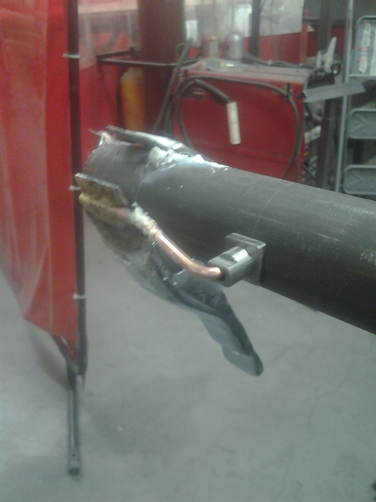
Braze ons are a really easy way to ruin a nearly finished frame. Done improperly or attached at the wrong location, they can create a weak spot in the bike tube that can crack and ruin the bike. Worse yet, this crack can appear after only a month or two of use. I attached downtube shifter bosses to one of the first frames I built up. I rode it back and forth to my day job, 15 miles each way. One morning, I started to hear a creak from my bike. I still had 4 or 5 miles to go, so I kept riding. The frame started to feel a little looser as I approached work. When I arrived at the office, I noticed a spiral crack working it’s way around the downtube from the area right next to the downtube shifter boss. I had to take the train home that day. When I cut out that section to fix the frame, I traced the crack to two sources. The downtube shifter boss was attached in the thinnest section of the tube, and I had brazed it on with bronze filler metal instead of silver solder. I don’t know which of these mistakes caused the failure, but I didn’t repeat either of them again.
If you’re going to braze on your braze-ons, use silver brazing. Attach your braze ons in the thicker butts of the tubing if at all possible.
Purists will clutch their pearls, but adhesives are a better way to go. Metal to metal adhesives ( JB Weld is my favorite ) are very effective with proper joint preparation, and they will not ruin the strength of your tubes. They’re also easier to use than silver soldering, and require zero practice.
Even the low heat of silver brazing will cause some distortion of the tube shape, making the tube less round. This is more of a problem with TIG welding and fillet brazing. To make your headset, seatpost, fork crown race and bottom bracket fit properly, you’ll need to do some post welding machining. Most of this machining can be done with hand tools. The easiest is the seat tube. Seat tubes need to be reamed in order to have the seatpost fit properly. The seatpost reamer allows the builder to remove just enough material so that the seatpost has a nice sliding fit with the seat tube. If the fit is too loose, the frame isn’t as strong and the seatpost clamp isn’t as effective. If the seat tube inside diameter is too small, the seatpost won’t go into the seat tube, or will be a super tight fit that’s likely to get stuck.
To ream the seatpost, put the frame in a repair stand, remove any removable seatpost clamp, and put some cutting oil on the seatpost reamer. Turn the reamer clockwise while pushing it into the tube. It will cut away a small amount of the inside diameter of the seat tube, so the seatpost fits just right.
Remove the reamer while continuing to turn in clockwise. Turning the reamer backwards will dull the cutting edges.
Reaming and facing the head tube is a similar process. It requires the right size reamers for your head tube and headset combination. If you’re using a press fit bottom bracket, reaming and facing the bottom bracket is the same. If you’re using a threaded bottom bracket ( which you should!) chase the existing threads in your bottom bracket shell with a bottom bracket tap set.
Park Tool is the biggest manufacturer in the US of these tools. I’ve also used Cyclus tools and IceTools. It’s also possible to buy reamers in just about any size from your favorite machine tool supplier.
Cold setting and Frame alignment
Keeping weldments straight is by far the hardest part of welding stuff. Because of the heat in the process, there frame experiences local thermal expansion and contraction anywhere you heat it up. This causes the phenomenon known as welds “pulling.”

Image from WeldingEngineer.com
Super tight joint fitup helps to mitigate this problem, but it’s still there. Ideally, you’d check your frame on a surface plate at various points in the welding process to bend it back into alignment or go over your joints again with the welding or oxyfuel torch. I have heard this referred to as “wizard wanding.” Manufacturers who need really flat weldments with minimal variation will go to great lengths to control those welding processes. They might have preset welder settings, super detailed instructions for how long any segment of weld can be, what order to weld each segment in, and so on. If you’re not already welding at a professional level, just go for it and accept that your frame is going to dance around a little bit.
There are tools to cold set dropout alignment and to check the frame alignment. Park Tool also sells a frame bending tool. I’ve used it, it works. You may well need it for your first couple frames.


 Marissa, (pictured) is not the sculptor in question.
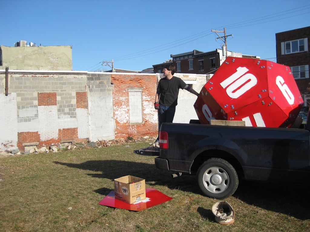 Not knowing anything about art, big/red/shiny was very much in earnest.