Now that you’ve designed your dream frame or copied a bike you like, It’s time to actually join the tubes. There are three main options: TIG welding, Fillet Brazing, and silver soldering. You could also bond them with adhesives I guess.
A quick aside – Most of what I know about material science.
Metals are nice to design with because they have nice, uniform material properties. That means that given consistent geometry, they’re equally strong in every direction. These properties come from the alloy composition of the material. The alloy composition is the mix of atoms of different elements that are in the metal. For example 4130 steel contains :
Component Wt. %
Carbon (C) 0.28 – 0.33
Chromium (Cr) 0.8 – 1.1
Iron (Fe) 97.3 – 98.22
Manganese (Mn) 0.4 – 0.6
Molybdenum (Mo) 0.15 – 0.25
Phosphorus (PMax) 0.035
Sulphur (SMax) 0.04
Silicon (Si) 0.15 – 0.35
That’s a lot of elements. It’s interesting that we call 4130 ChroMoly for Chrome and Molybdenum, but they only make up a maximum of 1.36% of the material by weight.
For a given material composition, there can be a range of material strengths that are based mostly on the grain size of the metals. In cast metals, the grain sizes are at their largest and the material is at its lowest energy state. That’s because the grains have lots of time to shed heat and kinda relax into great big grains. As the material is worked or heat treated, the grains of the metal get broken into smaller pieces, which are stronger. This is why forgings have superior material properties to castings. When you weld two pieces of metal together, the area next to the weld will be the weakest part of the joint. This is due to two factors: You (almost always) add material when welding, so the weld itself is thicker. The weld filler metal is often a different alloy than the parent metal, and it’s designed to be strong without additional heat treatment. The area right next to the weld doesn’t get any extra metal but it does see all the heat. This area is called the heat affected zone, and it ends up being the weakest part of the joint because the parent metal gets annealed. This is why destructive weld testing requires that the weld be stronger than the parent metal. The weld has a built in advantage of strength and would be a really poor quality weld to break before the parent metal.
OK – that’s almost everything I know about materials science.
Done properly, silver soldering and fillet brazing will not anneal the tubes of your frame, so you get all the material strength of the tubes. TIG welding will always create a heat affected zone, because the metal becomes liquid, which is by definition above the annealing temperature. Modern tube alloys designed for TIG welding will retain their material properties if they aren’t excessively heated. I believe they’re called air hardening. For a comparison of materials within one brand, check out this Reynolds design guide. How much heating is excessive? I’m not sure, because I’m not a materials scientist. Shoot for the narrowest heat discoloration from TIG welding and you should be OK.
The safest way to join your tubes is with lugs and silver soldering. Lugs are those fittings between the tubes on cool old bikes and Rivendells. Lugs are great because they constrain the angle of the two tubes and they allow you to join the tubes with silver solder. Silver solder is basically metal glue that creates a metallurgical bond between the three pieces of parent metal(s). It also has a melting temperature that is below the annealing temperature of the tubes you’re using. That means that the tubes won’t be weakened by the heating of silver soldering. This process is also called silver brazing. The two terms are used interchangeably.
Lugs are also sometimes a hassle because they constrain the angle between the two tubes being joined. That means that if you need half a degree of adjustment, you might be out of luck, or you might need to bend the lug.
Lugs are also a neat way to get really artistic with your frame, as you can file and shape them to be cool and frilly with lots of embellishment. I’m not crazy about the amount of handwork this requires, so I tend to avoid it.
One nice trick with lugged joints is the ability to pin them. This acts like a tack weld or braze, but you can take it apart. Miter the ends of your tubes and dry fit the lugs. You can do this in a fixture or relative to your flat surface. If you’re using a full scale drawing, then you can put the whole frame on top of the drawing to make sure it’s the right size and shape (I call this “looking like the picture.”) At this point, your lugged frame is just the right geometry, and it would be really nice if it stayed there, except that you have to pull it all apart to coat everything in flux, which you probably don’t want to drip all over your full scale drawing or nice reference flat surface.
How to solve this problem? Pin the lugs. Use an automatic center punch to make a divot so your smallish drill bit doesn’t walk, and then drill a hole through the assembled lug and tube. Then you firmly but gently drive a tapered pin into the hole, and it creates a reference feature that will lock the alignment. You can take the pin out, pull everything apart, slather flux all over it, reassemble and re-pin, and everything will be in the right place. A side benefit is that the pins can help to mitigate distortion from the heat of brazing. Even though you’re not melting the metal, it still expands and contracts with temperature. There are a couple options for this, Cycle Designs sells a kit with instructions. Another solution is borrowed from assembling machine tools and uses tapered pins like these from McMaster. Over the lengths formed by the combination of the lug and tube, a single drill hole is adequate. If you wanted to really go overboard, the tapered pins from McMaster are sized to be used with tapered pin reamers.
Fillet brazing is a nice middle ground for joining bike tubes. It’s not very difficult, allows any joint angle you want, and is very strong. It requires more finishing hand work than tig welding, but is much easier. Fillet brazed joints are typically sanded smooth on custom bikes. This has the benefit of hiding imperfect brazing technique. If you’re like me and you don’t like hand sanding stuff, practice until your brazes look like a clear coated Brompton. Donezo.
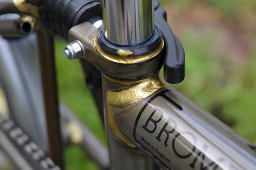
Photo credit: Lovely Bicycle
Tig welding is the most flexible way to join bike tubes. It’s also the most dependent on operator skill. (That means it’s the hardest.) TIG welding is the most portable skill for other fabrication, and if you’re only going to buy one welder, it should be a TIG welder. Done properly TIG welding adds the least filler material and requires the least post weld handwork.
MIG welding
Wait, but I thought there were only three?!
MIG welding is super easy. It’s probably possible to make a workable bike frame with one but you’d have to use the thinnest wire and probably use heat sinks. If you do this, all the other bike builders will make fun of you. That might be a mark in the positive column. (?) It’s also a recipe for chasing a hole in thin walled tubing all along the length of the tube.
Tube mitering:
The most important part of welding is joint preparation. Good fit up sets you up for good welds and straight frames. That means the ends of your tubes need to be just the right shape, oriented properly, and the right distance from each other. I’ve probably thought about this problem more than any other fabrication task. Here are some of the ways to go about it, roughly ordered from lowest tech to highest tech.
-
File the ends until they’re the right shape.
Pros: Very flexible, inexpensive. You only need a file.
Cons: hard to control, takes forever. Repetitive motion injuries? Good way to cut your fingers.
-
Use printed miter templates and a hacksaw / file.
Pros: Very flexible, inexpensive. Much easier than eyeballing it. Allows you to measure between mitered joints.
Cons: Drawbacks of hand filing. With practice, takes about 5 minutes per tube end. Good way to cut your fingers.
-
Use 3D Printed File guides
Pros: Very flexible and inexpensive. Easier to measure between mitered joints than paper templates. Easier to keep in phase than paper templates.
Cons: Drawbacks of hand filing. Requires a 3D printer. 3D printing is slow.
-
Commercial hole saw setups
Pros: Nice, cylindrical cut.
Cons: Easy to kink and destroy bike tubes with off the shelf hole saws. Hard to control feedrate. Can leave a nasty burr. Can be difficult to keep centered. Poor resolution on angle setting. Poor control of notch to notch distance.
-
Hole saws in a bridgeport
Pros: Nice, cylindrical cut. Gives you an excuse to buy a Bridgeport
Cons: Bridegeports are expensive, heavy, and hard to move. Takes up a lot of space. Tooling can be expensive or must be custom made.
-
Abrasive mitering
Pros: Nice, cylindrical cut. Better surface finish and size control than hole saws. Sandpaper is much less expensive than hole saws.
Cons: Smells bad. Ruins machine tools used for it.
-
Laser cut tubes
Pros: Effectively perfect joints. Someone else does it.
Cons: May require CAD models. May be difficult to source in small quantities. Depending on how you measure cost, expensive. Someone else does it.
-
Custom Hole Saw fixtures.
Pros: nicely controls angles and tube lengths
Cons: Cost. Requires hole saws.


