Dial Indicators are great! They’re very precise, easy to read, and have a standard form factor. They’re also really easy to use as a building block for larger gages.
Mueller Gageis the name brand for these types of gages, and their catalog is full of inspiration. They also make super nice commercial gages that you should just buy if they are within your budget.
I used to work in a shop where they used gages made from bar stock and dial indicators extensively, so I set out to build one of their style gages from memory. (Shout out to Tom Sidloski and Will Perry from Valley Manufacturing!)
My very derivative design is here. Drawings are here.
To use this style of gage, you need to create a gage setting master. In 35-125 we have several sets of gage blocks, and a couple sets of gage block clamps.
To create a master, select a set of gage blocks that add up to your desired nominal dimension. You should be able to “wring” them together, rubbing clean gage blocks together so that they stick to each other. Stack them up to create the total size you need and place them in a clamp. There are a couple different kinds of end caps that will allow you to create inside or outside diameter setters, or location gages.
Using your master setter, set the zero on the diameter gage. This is done by moving the gage clamp and turning the bezel. When properly zeroed, the gage should stop moving and change direction at zero on the dial when placed in the gage setter.
This gage will now give you a very repeatable and precise measurement for an arbitrary size. When measuring large parts or diameters where roundness variation is large, be sure to take multiple measurements and average the results.
Machining Aluminum is great, right? It’s easy to work with, cuts easily, and is inexpensive to buy mail order because it’s light, which cuts down on shipping costs.
It has nice material properties and is generally a favorite in machine shops.
So why is it so terrible to drill small holes in? Why do tiny drill bits even exist? They’re like an exercise in frustration. They break super easily, it’s hard to spin them fast enough, etc.
How does aluminum drilling go wrong?
Column bending and buckling. The drill goes in part way, some chips come out, and then for some reason the chips stop coming out as well and the drill bit just snaps right off. This is due to inadequate chip breaking. In order to move the chips up the flutes of the drill, you need to make them smaller pieces. This is done by a quick retract of the drill so that the chips move out of the hole.
Rebonded Aluminum This can be caused in two different ways. Very small, powdery chips are produced by drilling with a low feed rate. Those chips are hot due to friction with the cutting tool, and they’re small, so they get close to their melting point. Those melty chips stick to the steel or carbide tool, and weld themselves on there. Now the tool is a steel/aluminum system instead of the original steel, so it doesn’t cut as well. This is often the cause of broken tiny drill bits in aluminum.
So what are some solutions?
First – proper speeds and feeds. If you’re running a manual machine and controlling the feedrate by hand, you need to match your feedrate to the drill RPM to get a proper feed per tooth. Even drills as small as .050” will still take a chip as thick as .001” per tooth.
For a quick reference on how fast to turn drills, consult fswizard.
Second – Cutting oil. It will lubricate the flutes of the drill so that the chips will move out of the hole.
Third – when drilling deep holes with a manual machine, it can be difficult to control the peck distance. Control the peck distance by moving the quill stop at every peck. The increments on the side of the stop are .001”, which is probably too fine for most drilling operations.
Last – Use a “sensitive drilling attachment.” It’s a drill chuck that spins with the spindle but will extend with hand pressure. This tool only allows you to control the peck distance if you use it at the end of its travel, which is unusual. Typically you just push lightly, feel it make a chip, and then retract the drill.
My lab has great sheet metal tools, but there’s a missing link between the CAD sheet metal unfolding and making a precise flat that will actually create your part, and that link is measuring the stretch each bend creates in the sheet metal material, which is determined by the brake tooling used. Here are some quick notes about how to determine it empirically.
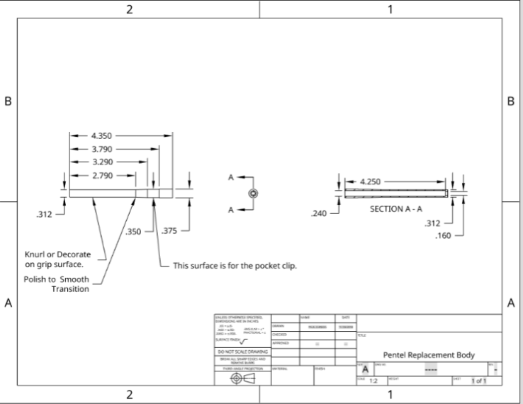
Once I saw this video, I knew I had to try to make my own using machine tools. Here’s my OnShape model with some drawings. It uses Pilot G2 cartridges. They’re my favorite and readily available. You’ll need some aircraft length drills and a 3/8 – 24 tap to make the body sections.
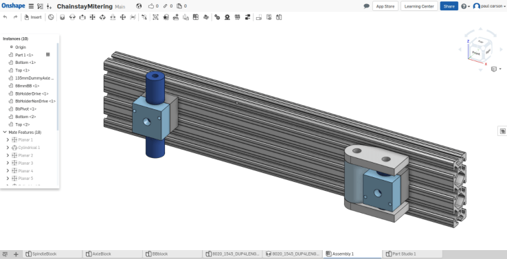
I use Solidworks at work a lot. I can’t afford my own seat of Solidworks. OnShape is basically Solidworks with better assemblies in a browser window. I like it for designing stuff on my chromebook, or from any computer where I have some time.
It’s free if you’re OK with making your designs public. Since I like to share my designs, I use the free plan. I believe that the paid one will let you keep your stuff secret.
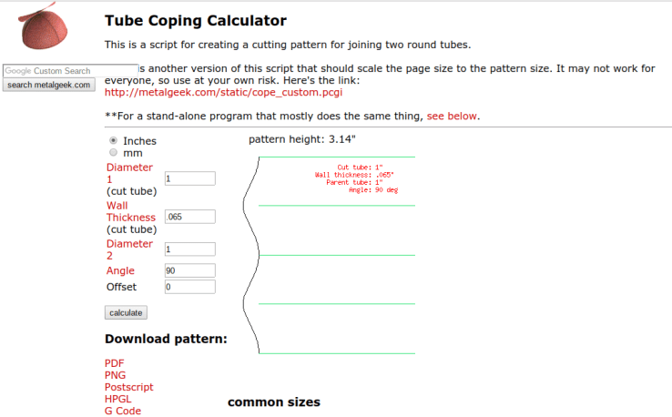
Welded fabrications from tubes are awesome. I like bicycles, but lots of other stuff gets made this way. Make your own awesome roll cage for a race car, or a motorcycle chassis, or other stuff that’s not a vehicle, I guess.
I’ve used this website a ton to make tube mitering templates. Put your sizes in the calculator, print out a pdf, cut out the shape with scissors and trace it onto your tube with a marker. it works great. With some practice, you can hacksaw and file a tube miter into shape in under 5 minutes. It’s not as fast as a hole saw, but it’s much less expensive.
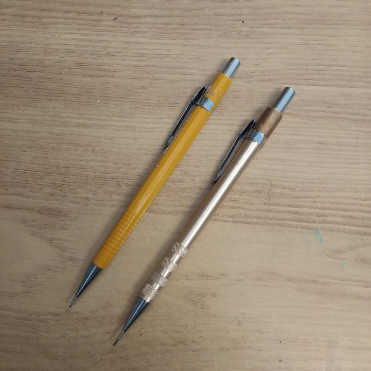
I like Pentel mechanical pencils, and have been using them for years. 0.9mm is my go to lead thickness because I’m a little hamfisted and tend to snap the thinner ones.
These metal housings are pretty easy to turn, and they make a nice weighty pencil. They also make nice gifts. I’ve posted the model and drawings on Onshape.


 I like Pentel mechanical pencils, and have been using them for years. 0.9mm is my go to lead thickness because I’m a little hamfisted and tend to snap the thinner ones.